I realized it might be interesting for some people to read about what I have on the bench. So this is the first in what I hope will be an ongoing series of project updates.
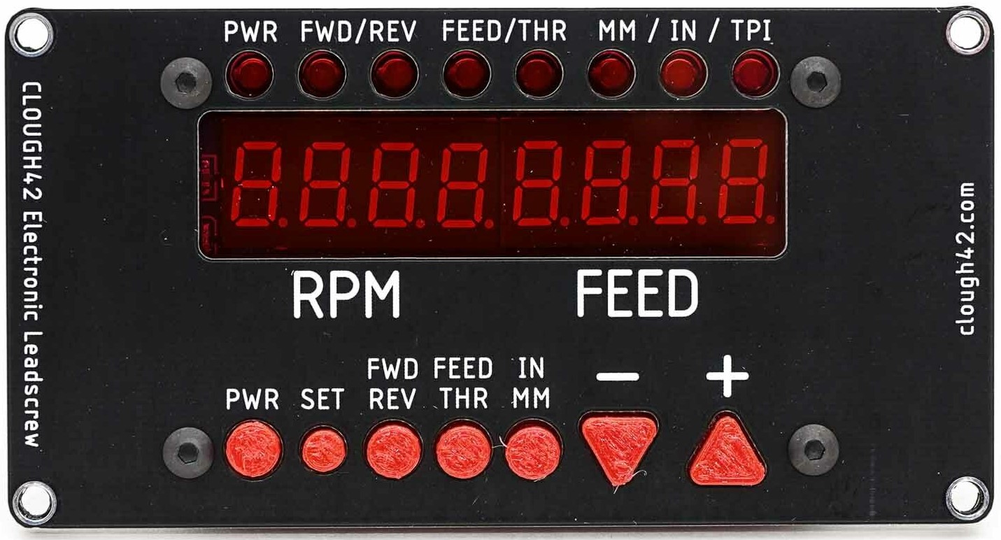
I’ve mentioned this before, but I am a huge fan of James Clough. His YouTube channel is full of consistently excellent videos. I first encountered him when Quinn of Blondihacks (another awesome YouTuber) mentioned his lathe electronic leadscrew project. I had a watch of James’s video series and realized I wanted to build one for myself.
So what is it? To explain that, we need to understand the function of a leadscrew (also written “lead screw”) on a metal lathe. Basically, its job is to advance the carriage – and with it, the cutting tool – at a fixed rate with respect to the rotation of the spindle. For operations like turning to a diameter, this is often a ratio like 0.005″ (five thousandths of an inch) per revolution. You can advance the carriage by hand using the hand wheel instead, but by coupling it to the motor shaft, not only is it less tedious, but you get a very smooth advancement of the cutting tool and hopefully a better surface finish.
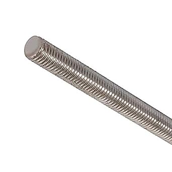
And that’s convenient, but where the lead screw really shines is when the relationship is something like 0.050″ of advancement per rotation, rather than 0.005″. Why? Because 0.050″ is 1/20th of an inch. And if we use a 60º cutting tool that advances 1/20th of an inch per revolution against a piece of stock that is 1/4″ in diameter, we can cut standard 1/4-20 threads.
Of course you can easily buy 1/4-20 threaded rod at the home center, so by itself this is no big deal. But what if I need something that’s got a half-inch of 1/4-20″ threads on one end and five millimeters of metric 8M1.25 threads on the other? You could, of course use a tap-and-die set to do this, but even someone with Tool Acquisition Syndrome as bad as I have it (see my shop tour to witness the extent of my problem) isn’t going to have taps and dies in all the combinations you’re likely to come across. For instance, Whitworth threads are a thing.
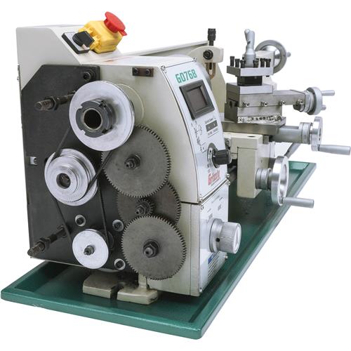
So it’s useful to be able to turn threads on the lathe. And my lathe, the Grizzly G0768, can indeed do so. However, it is a low-end lathe. And low end lathes control the rotational relationship between the spindle and the lead screw via change gears. (Nicer ones use a set of levers.) These are sets of gears in the headstock of the lathe that connect the spindle to the leadscrew, and in so doing set the rotational relationship between the two. There’s a chart on the lathe that shows you the combination of the two or three gears you need for the set of rotational relationships the lathe supports.
The problem is, changing them is a pain. They’re greased, so they’re messy. Removing them, finding the ones you need, dropping the screws on the floor six times, realizing you put them in the wrong one, finding the correct gears and putting those on, and then setting the backlash correctly so it doesn’t sound like gravel in a clothes dryer takes a skilled operator several minutes…and me a lot longer. And you might have to do this several times to make a single part. Like, you might need 0.005″ per rev to turn down to an overall diameter to turn one end down further, then switch to 0.050″ to thread one end, then flip the part and go back to 0.005″ to turn down, then change again to get to M1.25 metric threads on the other end. Completely reasonable to do so, of course, but frankly annoying enough that I have been avoiding doing it when I machine things.
Enter the electronic leadscrew. The idea here is to remove the change gears entirely, and instead drive the leadscrew with a stepper motor. The stepper motor is controlled by a microcontroller, which reads the rotational velocity of the spindle via a high-resolution rotary encoder. Introduce some sort of control interface and bam! Interactive control of the leadscrew advancement – switch from 0.005″ to 0.020″ (or whatever) at the push of a few buttons in seconds rather than minutes.
(If that doesn’t make sense, check out James’s video explaining the project.)
Do I need one of these? Nope. I could do the change gear thing – I’m into so many things and life with two kids is busy enough that I don’t do a huge amount of machining as it is. And I have a nice selection of taps and dies that means most of the time, I don’t need to thread on the lathe at all. But an electronic leadscrew is cool, and I want to make one. This website could just as easily have been called “get obsessed and make things you don’t need”, and so I am building an electronic leadscrew because it interests me and I want to.
Of course I could do this myself, from scratch. But frankly, I’m still a fair beginner when it comes to electronics and motors. I’m sure I’d learn a lot in trying to figure it out, but I figured I would also learn a lot by assembling James’s kit, not to mention throw a few bucks towards a guy who’s doing great work and get done and on to other projects way faster. And I have what I think is a really interesting project that learning more about motors and electronics will really help with. More on that in the future.

So I’ve been working on it as my main project since before I started this site. I’m now at the point where I have all the electronics assembled and all the necessary cables made. I put it all in a nice enclosure. I even 3D printed a motor mount for the stepper motor, which was a fun little project in and of itself that I might talk about at some point.
But.
It doesn’t work. Despite the fact that at one point I had everything working on the bench – I could turn the rotary encoder by hand and the motor would rotate in sync. Apparently, somewhere along the way to getting everything in the enclosure, I messed something up. I’m not really sure where.
And that’s my status: machine not working. But hey, that’s expected. As it says on Evan of EvanAndKatelyn‘s shirt:

At one point I thought it was the microcontroller, because I couldn’t even get a simple “blink the LED” program to run. So I ordered new one. And that one wouldn’t run the blink program either. At which point I realized that I had a bug in the program. (Software: it’s always the software.) What’s doubly amusing about that is I previously made basically the same mistake with the interface board, and bought a second one of James’s kit. So I now lack only a motor to make a second one of these, something I have absolutely no use for, owning only the one metal lathe. (For now. Send help.) I find this highly amusing. But also convenient, since now I can use the second interface board to make sure that’s not the problem. And on it goes.
So that’s all for now. I hope that was useful or at least interesting to some of you. I have a video in the works that will show my progress to this point – I just need to finish editing it. I will, of course, post further updates as I go. If you feel so inclined, leave me a comment and let me know what you think. Thanks!

6 thoughts on “Project Update: Lathe Electronic Leadscrew”